- Metal is very cold when the air is 14 degrees, and an excellent conductor of heat. It will, in fact, suck all the heat out of your hands. This is not safe when you are outside atop a 15′ aluminum tower.
- Heat conduction goes both ways. You should never turn on a heater on one side of a piece of metal, and then touch the other side to see if it’s hot. It is. Even if the air outside is only 14 degrees. You’ll still burn some fingerprint right off your finger.
- When snow reaches the top of a water spillway which you know to be about a foot deep, stepping in it will result in snow going over the top of your otherwise waterproof boots.
- Just because you push water into one end of a hose does not imply that it will come out the other. In fact, it does not imply that it will come out at all. I have, in fact, no idea what happens to it.
- The mister nozzle does not work 🙁
Monthly Archives: January 2007
Completely unnecessary, but a lot of fun to watch!
CakeBot (via hack-a-day)
College male seeks more heat in relationship
Dear downstairs neighbors of University Heights Apt 60,
I just wanted to drop you a note to thank you for running your heat earlier this year during the cold snap before Winter Break. Dave and I very much appreciated your generous donation of your unused BTUs.
That said, I think our relationship has been moving in a new direction lately, and I’m not comfortable with it. In fact, it’s been getting downright chilly. Frigid, even. I greatly fear for our continued friendship if you are not prepared to turn up the heat in our relationship a little bit. And I think you know what I mean by “turn up the heat.”
Now. I’m freezing.
Always Yours,
Colin
P.S. – Sorry about the noise. Nate bought a new subwoofer, and it’s fun 😀
Howto: Mythtv SNES Joystick Control
Update: Why oh why can’t Blogger preview my post in the *actual* stylesheet of my blog? I seem to remember WordPress doing this… if so, I must switch. ASAP.
I’m back down in Madison, and in the midst of unpacking all my junk after moving down here from home. One thing that Nate & I set up right away is my HTPC, an Ubuntu-based MythTV box. Unfortunately, I noticed over winter break that my homemade serial-port IR receiver has given up the ghost, so I can no longer control MythTV from my universal remote. I’ve ordered the parts for a USB IR receiver, but as I mentioned earlier, my soldering iron has also given up the ghost…
So, what to do in the interim? Well, there is a keyboard attached to the Myth box, but it doesn’t reach the couch. Enter the SNES controller and MythTV joystick control. Here’s how I got it to work:
Goal
- Control MythTV from an SNES controller (or any other gamepad)
Required Software / Hardware
- MythTV (I believe any version since 0.17 will work)
- SNES controller connected via parallel port adapter and the gamecon driver (see Documentation/input/joystick-parport.txt in the Linux source tree)
-
jstest(Optional, available on Ubuntu in the “joystick” package)
Determining joystick layout
The first step in writing a MythTV joystick configuration is to determine the exact layout of your joystick, as Linux sees it. Specifically, we need to know what axes (and axis values) and buttons correspond to the controls on the joystick.
If you’re using an SNES controller with the gamecon driver, I’ve done the legwork, and you can skip to the next section below, using my example configuration. (Obviously you should test it and make sure it works.)
To determine the layout of your own joystick, you can use the optional jstest program mentioned above. You can install it on Ubuntu from the joystick package (you will need the universe repository enabled):
$ sudo apt-get install joystick
Run jstest and record the axis numbers and values, as well as button numbers, that correspond to all the controls you wish to use on your joystick. jstest requires a parameter of the joystick device to open. For example, I run jstest like this for my first SNES controller:
$ jstest /dev/input/js0
jstest produces output for my SNES controller like this:
Driver version is 2.1.0.
Joystick (SNES pad) has 2 axes (X, Y)
and 8 buttons (BtnX, BtnY, BtnTL, BtnTR, BtnTR2, BtnSelect, BtnThumbL, BtnThumbR).
Testing ... (interrupt to exit)
Axes: 0: 0 1: 0 Buttons: 0:off 1:off 2:off 3:off 4:off 5:off 6:off 7:off
This tells me that the joystick as seen by Linux has two axes and 7 buttons. Pressing them in sequence changes the output, such as this output when I hold the directional pad to the left and press the “A” button:
Testing ... (interrupt to exit)
Axes: 0:-32767 1: 0 Buttons: 0:on 1:off 2:off 3:off 4:off 5:off 6:off 7:off
This tells you that the D-pad “left” direction corresponds to value -32767 on Axis 0, and that the “A” button corresponds to button 0.
Compiling a full list for your joystick would give you a mapping like this one for the SNES controllers & gamecon driver:
| SNES Button | Linux joystick mapping |
|---|---|
| D-Pad Up | Axis 1: -32767 |
| D-Pad Right | Axis 0: 32767 |
| D-Pad Down | Axis 1: 32767 |
| D-Pad Left | Axis 0: -32767 |
| A | Button 0 |
| B | Button 1 |
| X | Button 2 |
| Y | Button 3 |
| L | Button 4 |
| R | Button 5 |
| Select | Button 6 |
| Start | Button 7 |
Writing the MythTV JoystickmenurcConfiguration File
Now that you have the logical layout of your joystick in hand, it’s time to configure MythTV itself. This is done by means of the joystickmenurc configuration file, located at ~/.mythtv/joystickmenurc for the user that mythfrontend is launched under. This file will instruct MythTV as to which joystick device it should open, and then provides a mapping from the joystick layout to the keyboard strokes for MythTV.
joystickmenurc Format
As described in the formatting section of the Joystick Control page on the MythTV Wiki, the format for the joystickmenurc is as follows:
devicename <devname>- Specify the name of the joystick device to use, (e.g. /dev/input/js0)
-
button <num> <keystring> - Send
keystringwhen buttonnumis released -
chord <cnum> <bnum> <keystring> - If button
cnumis down, and buttonbnumis released, sendkeystring -
axis <num> <from> <to> <keystring> - If axis
numgoes into the range offrom–tosendkeystring
Example joystickmenurc for SNES controller
I think the formatting is best explained by an example. Below is the actual ~/.mythtv/joystickmenurc file I use on my system, with commenting explaining exactly what is intended and how it works. If you use an SNES controller attached via the gamecon driver to /dev/input/js0, this configuration should work for you as-is. Simply drop it in your ~/.mythtv directory and relaunch mythfrontend. For everyone else, feel free to use this as a template, or see the Joystick Control page on the MythTV Wiki for an example of an Xbox configuration file.
# ~/.mythtv/joystickmenurc
# Joystick menu config file
#
# Created 1/21/2007 by Colin McCambridge
# based on instructions at http://www.mythtv.org/wiki/index.php/Joystick_Control
#
# This joystick menu configuration controls MythTV with an SNES
# gamepad connected via parallel port and the gamecon driver.
#
# Controls:
#  SNES Pad            Keypresses       Joystick Device
#  --------            ----------       ---------------
#  UP/DOWN axis        Up, Down         Axis 1: U -32767 D 32767
#  LEFT/RIGHT axis     Left, Right      Axis 0: L -32767 R 32767
#  B                   Enter            Button 1
#  Y                   Esc              Button 3
#  A                   P  (Play/Pause)  Button 0
#  X                   S  (Guide)       Button 2
#  Start               M  (Menu)        Button 7
#  Select              I  (Info)        Button 6
#  Left Top            Page Up (REW)    Button 4
#  Right Top           Page Down (FF)   Button 5
#

###########################################################
#
#    SNES Gamepad Device
#
###########################################################

devicename /dev/input/js0

###########################################################
#
#    D-Pad
#
###########################################################

#Up
        axis    1       -32767  -1      Up
#Down
        axis    1       1       32767   Down
#Left
        axis    0       -32767  -1      Left
#Right
        axis    0       1       32767   Right

###########################################################
#
#    Buttons
#
###########################################################

#A ==> Play/Pause
        button  0       P
#B ==> Enter
        button  1       Enter
#X ==> Guide (S)
        button  2       S
#Y ==> Exit (Esc)
        button  3       Escape

#Start ==> Menu (M)
        button  7       M
#Select ==> Info (I)
        button  6       I

#Left Top ==> Rewind (PgUp)
        button  4       PgUp
#Right Top ==> F.Fwd (PgDown)
        button  5       PgDown
Final Notes
For making your own joystickmenurc file, you may find the MythTV Default Keybindings, or the more abbreviated Remote Control Buttons list handy references as to the control operations you can define.
For an exact list of valid key names to use (e.g. “Escape”) refer to the Qt documentation for the Qt.Key enum. This document lists key names in the form: “Qt::Key_Escape“, use only the name following the underscore.
Note: there is an undocumented discrepancy regarding the keys Page Up and Page Down. While the Qt.Key enum lists them as PageUp and PageDown, they can actually only be specified as either "PgUp" and "PgDown", or "Page Up" and "Page Down" respectively. See messages 3 and 4 of this email thread for reference, or view the relevant Qt source file (especially the keyname[] array at line 89, and method decodeString at line 388): qkeysequence.cpp
Building a Power Supply: Phase 1.5
Subtitled: On Hiatus
My new Weller WES-51 (from back in October) was finally used for the first time on Monday. It functioned for all of 2 hours or so. I believe a faulty transformer is to blame.
I followed the directions for troubleshooting the device up to the point where I sliced an inch-long gash in my thumb with a blunt screwdriver.
I no longer have a soldering iron and am not yet comfortable typing with my left thumb, let alone assembling circuitry.
It seems I should have taken Paul’s advice more closely to heart.
So I guess, stay tuned?
Building a Power Supply: Phase 1
Well, as alluded to in earlier posts, I have been working on a project over this winter break. I am designing and building a three-output adjustable linear bench power supply. I think that about 2 people who read this will have any idea what that means, so here’s the basic idea: If you want to skip all the back-story, please just take a look at the pictures instead. 🙂
Most engineers are engineers because they really like to tinker with things. Maybe that isn’t actually true of “most” engineers, but I think it’s true of all the cool engineers. 🙂 Anyway, electrical and computer engineers tend to like to tinker with electronics. For instance, this strange tinkering bug might possess them to build a cable to link their universal remotes to their computer for brain surgery. The end product of which, might, perhaps, allow the remote to display “MythTV” (why that?) on screen instead of “TV” or “VCR”…

…Not that anybody you know would do that…
Anyhow, in the course of messing with electronics, you need a fair number of tools. A digital multimeter to show you how many volts something is at, or how much resistance is in a given wire, is absolutely essential. So is a soldering iron to make changes to circuits. (mad scientist’s evil grin >:-D)
Another essential is some sort of power source. That’s where my project comes in. Most devices you buy (think digital camera, cell phone, remote control, answering machine, electric pencil sharpener) have either batteries, a wall plug, or a combination of both as a power source. Generally, devices which have a wall plug (such as your cellphone charger) convert the AC electricity in your house to DC electricity, like that which comes out of a battery. That’s all well and good, and every device is customized to use whatever precise form of DC voltage it needs, but what about building your own devices? Or powering up broken stuff? You (the electrical/computer engineer) would have to have one of every kind of power source, or at least the most common types, on hand.
Enter my adjustable bench power supply. (You knew that whole mess was going somewhere, right?) This is (/will be) a device that plugs into the wall, and converts the AC electricity available there into DC electricity at any voltage. Thus it can be made to work with any circuit’s needs. There are limits of course, though I haven’t completed enough of my construction to know the final specs yet. I expect to be able to provide about 1.0 amp at 1.5V to 30V from one output, and 1.0 amp on each end of a tracking ±1.5V to ±15V. Non-EE Translation: the supply will have three outputs. The first will be able to simulate anywhere from 1 to 20 AA batteries in a row, including “fractions” of batteries. The second output will be able to simulate from 1 to 10 AA batteries (adjustable separately of the first output). The third output will be adjusted simultaneously with the second, and will provide negative1 to 20 AA batteries, at the exact same voltage as the second output. I.e., if the second output is +9.5V, then the third will be -9.5V.
So enough nerd-babble. All anybody really cares about is pictures, right? Fine. Since I’ve only been prototyping for one day so far, I have only tested part of the final circuits. (For the electrically-inclined, I haven’t included the transformer or rectifier stages yet.) BUT, here is what I have so far:

This is the simplest adjustable voltage supply. The little blue box is the control (a potentiometer). Proof that it works [468K MPEG4]

This is the next iteration, with a digital circuit, a pushbutton switch, and three preset voltage levels. I’m rather pleased with how this turned out, though I still have some work to do on the switch, as it sometimes switches 6 or more times per button press (for the EEs: I tried using a RC debouncing circuit, until I realized that leaves the voltage level in the no-man’s zone around 1.2V for way too long. Oops. Now I just have a pull-down resistor, and the normally-open switch ties the clock pin on my CMOS 4017 to Vcc.)
Enough of that: I saved the best (IMHO) for last. Proof that this circuit actually does something [520K MPEG4]. In this clip I press the pushbutton several times. Note that the voltage switches from about 3.25V to 5V to 8V, then cycles around again. Also note the LEDs that track which voltage is currently selected 🙂
Alright, I’ve already wasted way more time on this blog post than I meant to. Back to the bench!
Life's Little Mysteries
Life’s Little Mysteries
Originally uploaded by CCmcGeek.
So that’s how bite-sized Tostitos are made!
Resistors capacitors and diodes oh my!
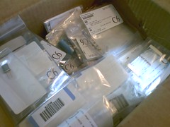
Resistors capacitors and diodes oh my!
Originally uploaded by CCmcGeek.
My $97 order from mouser came in today! Now I can start building my power supply… just as soon as I finish cleaning my room. 🙁 But seriously, who knew FedEx delivered on Saturday?? How awesome is that?
Gotta Fly Red-Eye While I'm Still Young
SFO 00:35 6/8/07 –> MSP 06:03 6/8/07
MSP 10:25 6/8/07 –> GRB 11:39 6/8/07
GRB 12:05 6/10/07 –> MSP 13:13 6/10/07
MSP 14:20 6/10/07 –> SFO 16:16 6/10/07
Cousin Tracy’s wedding
Just need to navigate Caltrain + BART now.
Howto: Resize Your Own Watch
I haven’t put too many posts up here that are actually helpful to anyone else in any way, so I thought I should start working on that. This may or may not be helpful to anyone either, but what the heck, I already had the pictures…
Disclaimer: I am not a jewelry / watch expert, and in fact know next to nothing about them. What I present here worked for me, but I make no claim that it will work for you and take no responsibility for your actions and any damage they may cause. 🙂
Back-Story
So why am I resizing a watch band, of all things? Well, my parents bought me a Seiko watch for Christmas during my senior year of high school, which I like very much. Unfortunately, wearing it for several years (and drumming with it on) popped one of the hands off one of the smaller dials, and that hand now rattles around freely under the crystal, frequently getting stuck under other dials and jamming the watch up:

Note the alarm dial (bottom) of the old watch is missing a minute hand, which is located upside down jamming its second hand (left dial).
After sending it off to Seiko for a repair estimate ($162), we decided it wasn’t worth the money to repair, as it would be better spent toward the purchase of a new watch. Fast-forward several months, and I find my very same watch on Amazon.com for $105 (no longer available). I was pretty excited to have a chance to get it fixed, so I bought it. Fast-forward another week or so, and my new watch arrives. Three sizes too large for my wrist. Oops.
And so, here we are.
Goals
- Resize a watch band of the “pin-and-link” type seen above.
- Avoid fees to have it resized at the mall
- Avoid damage by the inept worker at the Younkers jewelry department
Tools
- Pentel 0.5mm mechanical pencil tips
- Thumbtacks
- 1″ Brad
- Light hammer
Steps
- First, take a close look at your watch and determine how many links need to be removed, and from which sides of the clasp. Keep in mind that you should try to balance the removed links from both sides, or the clasp will end up on the edge of your wrist instead of the back.
I had this step easy, as the old watch was fitted correctly to my wrist already as a model. In my case, I needed to remove 3 links total: 2 from one side of the clasp and 1 from the other. - The next step is to determine exactly which links you will need to remove to accomplish this, and which pins hold them in place. Generally, you will need to remove 2 pins (one from each end of the link(s) you will remove), and then replace 1 to rejoin the watch band.
- Removing and inserting these pins without a commercial tool for doing so is the tricky part, and why I am writing this Howto. So, on to the pins:
- On my Seiko, I started by removing one of the pins on the links near the clasp, in the direction indicated by the small engraved arrow:

- One method to remove these pins uses the tip from a 0.5mm mechanical pencil. Remove the tip and place it point up on a solid surface. Then press the watch down, aligning the pin with the pencil tip’s metal shroud. Apply force as vertically and firmly as possible.
This was the first method I tried, and though it worked for two of the pins I needed to remove, it destroyed 3 mechanical pencils by pushing the metal shroud into the tip. For this reason, I do not recommend this method.

- A second method is to use a thumbtack. Place the tack point-upward on a sold surface. Very carefully align the watch pin on the tip of the tack and press downward firmly. It is very important to keep the watch aligned so that you are always pushing directly into the pin, not at any angle. If you are not careful, the watch will slip off the pin, and if you’re like me, you’ll stab the pin a full quarter inch into the tip of your finger.
Despite the increased danger in this method, I found it to be the most effective, and though I did destroy another few tacks in the process, I was able to remove the remainder of my pins relatively easily.

- Once all the pins are removed, you simply rejoin the remaining watch band pieces by reinserting pins as necessary. This is the second significant challenge.
- When reinserting the pins, it worked best for me to insert them in the opposite direction I had removed them in. I attempted to insert the pin in the direction of the arrow the first time around, pushing the “bulge” in the pin through first, with the result of destroying the pin:

- It is possible to push the pin nearly all the way back in just by hand and pressing the watch against a table, but replacing the pin the last 1/16″ proved trickier. You would like to reposition the pin as it originally was, to minimize the risk that it will fall out.
- The best method I found for recessing the pin back to its original position was to tap it lightly with a hammer, via a nail. Place the watch on a solid board or edge of a table so that the edge of the watchband rests solidly on the surface. Then align a small brad (I used a 1″) with the stub of the pin sticking out, and rap it lightly with a hammer as shown:

- Repeat for all pins that you need to remove and replace to adjust the watch size.
- And that’s it!

Finished watch, down to size with minimal scratches.
Total bill of materials:- 3 mechanical pencil tips
- several thumbtacks
- one watch pin
- one stabbed finger


